Face-offsetting ( Thickness ) using MUIDrawManager

Hi there,

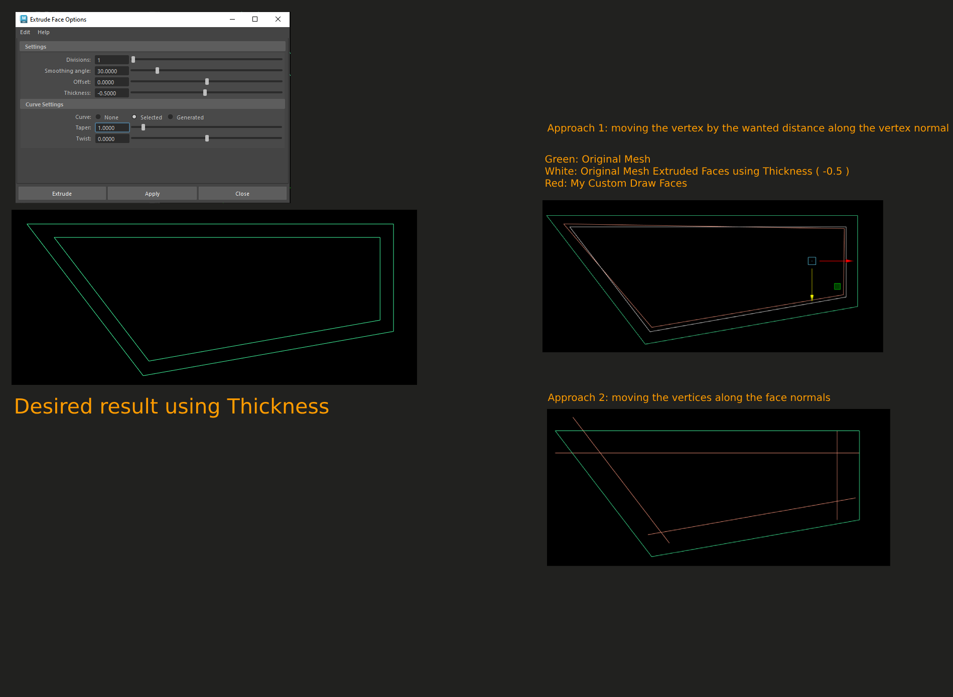
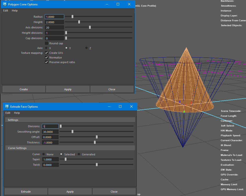
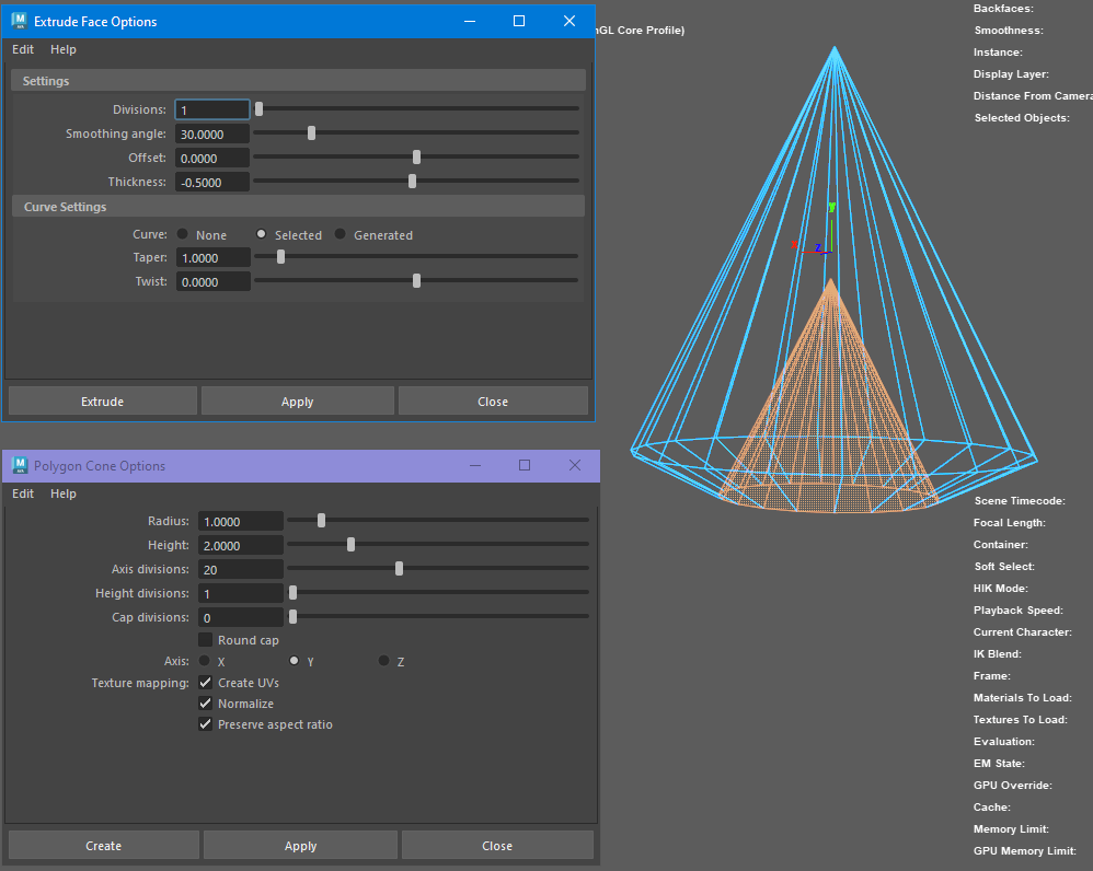
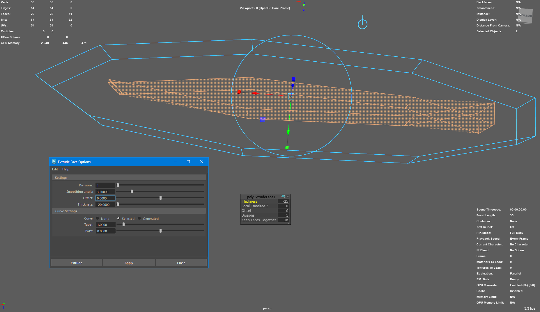
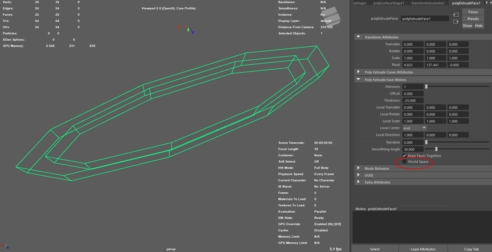
I have a poly mesh where I want to draw an offseted version ( a.k.a thickness ) using MUIDrawManager. The desired result that I am looking for is what Extrude/Thickness in Maya does. When using Thickness, the newly created vertices are displayed uniformly which I want do emulate.

My first approach was to move new vertices along the vertex normal of original mesh but that doesn’t give the uniform displacement.

Pseduo code :

MFnMesh fnMesh(objPath);

std::vector<MPointArray> displacedVertexPositions;
for (int faceIndex = 0; faceIndex < fnMesh.numPolygons(); ++faceIndex) {
	// Get the vertex indices for the current face
	MIntArray vertexIndices;
	fnMesh.getPolygonVertices(faceIndex, vertexIndices);

	// Move vertices along the face normal with the specified scale factor
	MPointArray faceVertexPositions;
	for (unsigned int i = 0; i < vertexIndices.length(); ++i) {
		MPoint vertexPosition;
		fnMesh.getPoint(vertexIndices[i], vertexPosition, MSpace::kObject);

		MVector normal;
		fnMesh.getVertexNormal(vertexIndices[i], true, normal, MSpace::kObject);

		// Adjust the displacement to account for the desired thickness or scale
		MVector displacement = normal * scale;

		// Move the vertex along the adjusted displacement
		MPoint displacedPoint = vertexPosition + displacement;
		faceVertexPositions.append(displacedPoint);
	}

	displacedVertexPositions.push_back(faceVertexPositions);
}

// draw wireframe mesh
for (const MPointArray& points : displacedVertexPositions) {
	drawManager.mesh(MUIDrawManager::kClosedLine, points);
}

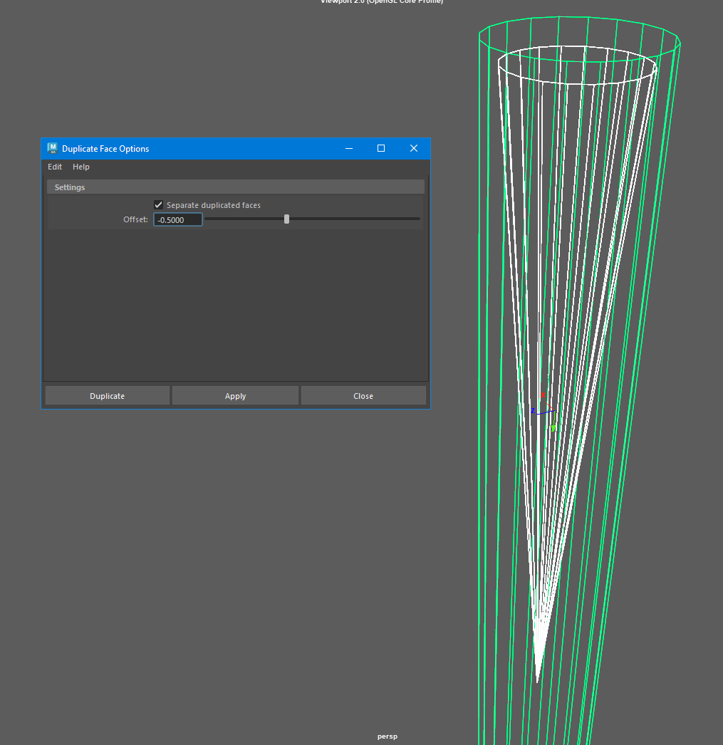
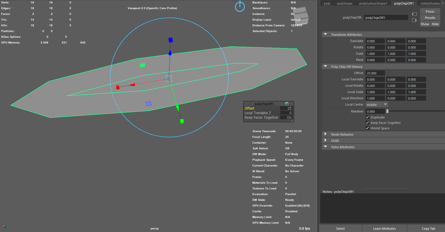
For the second approach, I am trying to move the new vertices along the Face center normal. The new vertices are displaced uniformly but not properly connected.

I am trying to figure out what I am missing here and if there is a better way to do this

std::vector<MPointArray> displacedVertexPositions;
for (int faceIndex = 0; faceIndex < numFaces; ++faceIndex) {
	// Get the vertex indices for the current face
	MIntArray vertexIndices;
	fnMesh.getPolygonVertices(faceIndex, vertexIndices);

	// Compute the face normal 
	MFloatVectorArray normals;
	fnMesh.getFaceVertexNormals(faceIndex, normals);
	MVector centerNormal(0.0, 0.0, 0.0);
	for (unsigned int i = 0; i < normals.length(); ++i) {
		centerNormal += MVector(normals[i].x, normals[i].y, normals[i].z);
	}
	centerNormal /= normals.length();
	centerNormal.normalize();

	MPointArray faceVertexPositions;
	for (unsigned int i = 0; i < vertexIndices.length(); ++i) {
		MPoint vertexPosition;
		fnMesh.getPoint(vertexIndices[i], vertexPosition, MSpace::kObject);
		
		// move vertex position along face center normal
		MPoint displacedPoint = vertexPosition + centerNormal * scale;
		faceVertexPositions.append(displacedPoint);
	}

	displacedVertexPositions.push_back(faceVertexPositions);
}

for (const MPointArray& vertPos : displacedVertexPositions) {
	drawManager.mesh(MUIDrawManager::kClosedLine, vertPos);
}

Any help is appreciated.

Just spitballing here, including some of my bad ideas so you can follow my thought process.

I’ll bet you can offset each edge and scale by some function of the dihedral angle across that edge.
If I were to guess, that function of the angle would boil down to something like
1 / dot(face1.norm, face2.norm)
I didn’t actually do the math, but it seems like a pretty good guess to start with :slight_smile:

Then for each vertex, you’d average the offsets from each incoming edge… maybe? That seems wrong somehow.
Maybe you could grab the “closest point of approach” for each adjacent pair of incoming edges, then average those points. That seems closer, but probably slower to compute. I wonder if there’s a fast way to do that? Maybe a least squares distance from all the edges? That sounds like something I could find on stackoverflow :smiley:
[edit] Yup: algorithm - 3d point closest to multiple lines in 3D space - Stack Overflow

Then I wonder if it would make sense to do some kind of weighted least squares and take the dihedral angles into account somehow? Or the angle that the adjacent triangles make with the vertex in question? Or maybe you could use cotangent weighting like they do in weighted Laplacian smoothing.


So, my first test would probably be the edge offset scaled by the inverse of the dot product. Then figure out how to find the point of least squares distances to all those offsetted edges. Then if that didn’t work exactly how I wanted, I’d start modifying the algorithm with some of my other suggestions.

Or maybe you’ll get lucky and somebody else will reply with some code, or an even better idea!

1 Like

The easiest way is to create geometry using the original “Extrude” command (with history), hide it and use the information for your needs, including drawing. :slight_smile:
But relying on the Autodesk implementation is not very reliable (Often non-deterministic behavior, or incorrect results).
For example:

  1. In this example, we seem to get the correct result:

  2. Let’s try again, but with a shifted vertex:

  3. Let’s try offset for the same cone:

  4. Let’s continue with the example of another cone:

  5. Remove the base from the cone and try again:

  6. Let’s try it using an oblate cylinder as an example:

  7. Don’t forget about the “World Space” option:

  8. At the same time, for a flat figure the result is correct:

You can continue endlessly…

I would start with a naive implementation:
I would create straight lines through offset normals and look for the intersection of these curves.
This is very quick and simple math.
With the subsequent complication of algorithms for: resolution of collisions, ambiguities, control of negative offsets, control of self-intersections (original and created geometry), etc.

Thanks tfox_TD and VVVSLAVA for replying quickly.

In my case, I don’t need all the edge cases or complexities where thickness fails. I am also dealing with only convex hull meshes with not too many faces.

I think finding the intersection would be the easiest solution.

But what if “THE” intersection doesn’t exist?
In fact, except for very specific cases, there will never be just one intersection.

For example, I just made 5 arbitrary triangles come to a point. Then I extracted each triangle, and offsetted each one along its normal. Then I scaled, added thickness, and booleaned them together. So this is the solution you get for doing exact face normal offsets.

Notice that the faces no longer come to a point. That’s why I was talking about all that “closest point of approach” and “least squares” stuff.
You absolutely CAN calculate where all those vertices are in the image, and then average them. It’s a lot of code to write to handle that. But on the other hand, it’s much more understandable than the least squares stuff.

1 Like

If your goal is not academic research or expansion of consciousness and skill level, then the method I originally proposed (“get the Maya to do all the dirty work for you”) may be applicable in some scenarios.

import maya.mel as mel
import maya.cmds as cmds
import maya.api.OpenMaya as om2
def maya_useNewAPI():
    pass
# or:
# maya_useNewAPI = True

# Prepare

# Let's create some polygon geometry for demonstration:
src_mesh = cmds.polyCylinder(name = 'Example_mesh_00',
                             r = 10, h = 10,
                             sx = 10, sy = 1, sz = 1,
                             ax = (0, 1, 0), rcp = 0,
                             cuv = 3, ch = 0)[0]
om2.MGlobal.unselectByName(src_mesh)

# Let's get OpenMaya MFnMesh for the created shape:
fn_mesh_src = om2.MFnMesh(om2.MSelectionList().add(src_mesh).getDagPath(0).extendToShape())


# Duplicate the original geometry:
# (We can create an Instance and Instance Leaf by specifying in the parameters: duplicate(True, True))
fn_mesh_copy = om2.MFnMesh(om2.MDagPath.getAPathTo(fn_mesh_src.duplicate()))
# Or we can create a copy of the mesh, under the original transform node:
# fn_mesh_copy = om2.MFnMesh(om2.MDagPath.getAPathTo(fn_mesh_src.copy(fn_mesh_src.object(), fn_mesh_src.parent(0))))
# Or we can create a copy of the mesh, under a new transform node:
# fn_mesh_copy = om2.MFnMesh(om2.MDagPath.getAPathTo(fn_mesh_src.copy(fn_mesh_src.object())))

# Additionally, we can disable the visibility of the duplicated grid in the viewport and outliner.

# Set of values for face extrusion:
src_num_polygons = fn_mesh_src.numPolygons
faces_seq_for_extrude = om2.MIntArray(range(src_num_polygons))
thickness = 1.0
offset = 0.0
extrude_together = True
translation = om2.MFloatVector()
extrusion_count = 1

# Extrude all the faces of the mesh:
fn_mesh_copy.extrudeFaces(faces_seq_for_extrude, extrusion_count, translation, extrude_together, thickness, offset)

# Remove unnecessary mesh faces:
faces_seq_for_delete = om2.MIntArray(range(src_num_polygons, src_num_polygons*2))
fn_mesh_copy.collapseFaces(faces_seq_for_delete)
fn_mesh_copy.updateSurface()

# Now we can save the data we need from this mesh for our purposes, and then delete this mesh.

# PROFIT!


# ***

# Or we can use this mesh directly for rendering:
# For clarity, let's rename the transform and shape of the duplicated geometry:
fn_mesh_copy_transform = om2.MFnTransform(om2.MDagPath.getAPathTo(fn_mesh_copy.parent(0)))
fn_mesh_copy_transform.setName('mesh_for_draw_00')
fn_mesh_copy.setName('mesh_for_draw_00Shape')
copy_mesh_full_path_shape_name = fn_mesh_copy.fullPathName()
copy_mesh_full_path_transform_name = fn_mesh_copy_transform.fullPathName()

# Hide the display of the transform and shape in the outliner:
cmds.setAttr('{}.hiddenInOutliner'.format(copy_mesh_full_path_shape_name), 1)
cmds.setAttr('{}.hiddenInOutliner'.format(copy_mesh_full_path_transform_name), 1)

# Set up the display of the mesh in the viewport:
# Leave only the wireframe display and change the color
# (If desired, we can enable the display of other data for this mesh.)
cmds.setAttr('{}.overrideRGBColors'.format(copy_mesh_full_path_shape_name), 0)
cmds.setAttr('{}.overrideColor'.format(copy_mesh_full_path_shape_name), 17)
cmds.setAttr('{}.overrideShading'.format(copy_mesh_full_path_shape_name), 0)
cmds.setAttr('{}.overrideEnabled'.format(copy_mesh_full_path_shape_name), 1)
fn_mesh_copy.updateSurface()

# There is a dilemma:
# If we don't want the mesh to be unselectable in the viewport, then the most obvious solution is to make the mesh a "Template".
# But then we won't be able to set unique colors just for this mesh.
# I don't know how to make a specific mesh "nonselectable" using the Python API
# but you can use the ugly and awkward method - scriptJob:
mel.eval('proc nonselectable(){select -d ' + '{0} {1}'.format(copy_mesh_full_path_shape_name, copy_mesh_full_path_transform_name) + 
         ';} $job_nonselect = `scriptJob -e "SelectionChanged" nonselectable`;')

# Disable execution of this scriptJob:
# mel.eval('scriptJob -kill $job_nonselect -force;')
1 Like

I feel attacked! :laughing: :laughing: :laughing:

1 Like

@tfox_TD - my HERO !

1 Like

@VVVSLAVA Appreciate posting the code! I will give it a try tomorrow. However, I am hoping that I can do all the work myself and find a simple solution to perform the uniform offsetting.

In my case, I will be only dealing with convex meshes with roughly around 1000 faces at most. This should reduces the algorithm complexity.

Once solution that I was thinking for getting uniform thickness:

1- Create a plane equation for each polygon ( e.g newell’s method )
2- Push these planes a long the face normal vector ( normalized ).
3- Do a ray-plane intersection by sending rays from each vertices towards these planes and record intersection points
4- Draw the recorded points

This may be out of league here, maybe it’s so “that goes without saying” so it’s too obvious to type it out, since @tfox_TD is here(I understand that when the masters talk they leave simple stuff out), that’s a long-winded way to say I might be pointed out the obvious one, but for step 2: shouldn’t the plane be scale up to make sure they do intersect?

Does your geometry consist only of triangles?
Or can you guarantee that all the polygons in your geometry are planar?

and for step 3: how do you determine the direction vector for the ray to shoot, so that the intersected point is the “uniformly extruded” result of that point.

But if you scale the plane at step 2, you can do plane intersect to get a line, and the end position of the two points of that two planes will definitely be landed on that line, and then next to get all the line intersected point, than those point should be the end result

The trick with this is that we don’t actually duplicate the mesh face. We make a mathematical object that can represent a plane. In the same way that an infinitely long line can be described by just a point with a direction vector, An infinitely large plane can be “all points perpendicular to a line that go through a specific point”. Since that’s a mathematical definition of an infinite object, we don’t need to scale!

That line we’re perpendicular to is just the face’s normal. So the face normal, and one vertex defines an infinite plane parallel to the face.

That’s a good question! I personally don’t think there’s a Good™ way to do that (hence me geeking out about alternate methods), but there are certainly “good enough” ways in practice.
I don’t know what home3d2001’s plans are, but there’s a couple different ways to calculate vertex normals. Or you can just use the maya API to get them if you don’t want to calculate them yourself.

“We make a mathematical object that can represent a plane.”<

I see, and I was really thinking about make new plane mesh so that I can use maya’s own ray cast function. How much faster to do it in pure math object?
or maybe not even in this case, just generally, is it almost always a better way to go about this kind of problem in math world.

I’ve written a UV shell auto rotate script for my work, but to query the uv shell’s edge vertices after each rotation(179 times to find the tallest bounding box) the script is really slow, like 0.6 second for one UV shell(each shell for the low poly at most 200 vertices average at 50-100), and I was planning on to rewrite it in pure math after the first query and turn them into numpy or something. How much faster am I looking at

It’s already all in the math world :slight_smile: It just boils down to what you can ignore when you narrow the scope of your problem.

Maya’s raycast has to do a LOT of extra things. It has to search along the ray and somehow ignore all the triangles it has zero chance of hitting. There are ways to make that search not so slow computationally (usually based on Bounding Volume Hierarchies), but it’s still complicated. And then, once its narrowed down to the triangles close enough, it still has to go through the pure math part of intersecting the ray with the plane of each triangle, then checking if the intersection is inside or outside the triangle.

If we roll our own algorithm, though, we know exactly which planes we need to test at any given time, and we don’t have to check if our intersection is inside or outside the triangle. We just have to intersect our ray with all the planes, and get the closest hit. Of course, there’s a tradeoff, because we have to actually write the line/plane intersection code ourselves. But it’s relatively straightforward, and there’s a bunch of hits on google. The math equation is only like 12 symbols long.


It sounds like you’re trying to find the longest axis of a shell around a given set of points, and then rotating to that axis. I’m fairly certain that’s equivalent to finding the minimum area bounding box for a set of points. Or maybe finding the minimum bounding circle? Either way, there’s a LOT of stuff out there on that. But honestly, for artist purposes 1 degree isn’t gonna make or break anything, and just checking 180 options will be more than good enough… Though you probably only need to go through 90 degrees and just check for the tallest OR widest bbox.

But no matter what you’re optimizing for, with some clever numpy you could get to less than .1s total with mesh sizes like that.

It may be off-topic for this thread. But definitely ask when you get to it. I love optimizing numpy stuff!

that’s exactly it, the actual script check every 2 degree for 180 degree, because I want it all to go ‘up’, and added a near circle detection, to skip the circle uv shell. So basically changed it to query 89 times, and it’s faster by exactly 2 times to 0.3 second :sweat_smile:
for 0.3s per uv shell there’s still an awkward waiting when I demonstrate the script to process a prop model.
For less than 0.1s, I’ll definitely find time to optimize it

Sorry to all future reader if I get this thread to go off-topic~